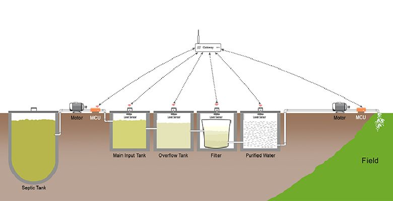
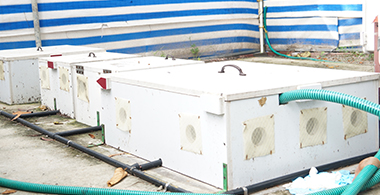
Fully automated the Gate Foundation funded waste water treatment for Agriculture research project. Water from the septic tanks are pumped into a tank and passed through a series of tanks to undergo biological treatment. Water so purified is then used to irrigate plants. Waste water goes through four tanks. A collection tank, overflow tank, filtering tank and then purified water collection tank.
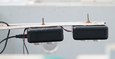
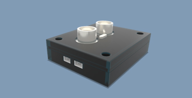
All the four tanks currently have ultrasonic level sensors planted in them. Level sensors in tank 1 and 2 constantly checks the water level in the tank. Deployment also have two actuators called motor control units (MCU). MCU’s control the two water pumps; one controls the pump near the septic tank from which the waste water is sourced and another one manages the water pump that pushes the purified water onto the farm. There is also a Gateway module where both the communication management firmware (PChartZ Layer) and the application software is hosted. Gateways “Pchartz layer” will constantly check whether all the sensors and actuators are healthy and alive. Application that controls the whole process receives necessary data for decision making from the communication layer (PchartZ layer) and will take appropriate actions based on the sensed values.
Application hosted at the gateway will compare the level sensor values from tank 1 against predefined lower threshold value, and will turn on the motor to draw waste water from the septic tank. Application will monitor the level sensor values from Tank 1 and 2 and will cut off the motor when the predefined upper limit is reached. Likewise, when the purified water collection tank reaches its upper threshold, the application will kick start the water pump to discharge the water onto the field. When lower threshold value is sensed in tank 4, the application will send appropriate messages to the MCU to cut off the motor. Level sensor in tank 3(filter tank) will also raise an alarm in case it senses any increase in water level. Usually water level in this tank should remain static. This should indicate possible spillage due to malfunctioning of the filter. All the wireless sensors and actuators used in this deployment are developed in our centre and hence we can fine tune their performance. All wireless devices engage a wireless protocol called ZigBee for adhoc network formation. The ZigBee modules and the gateway modules were all fully designed and developed in house by the team itself. We will also provide live visualization depicting the real time status of the entire system.
It can be viewed in a browser through our public server or can be installed as an android App. Data from all the sensors and actuators are stored at the gateway for processing and is eventually pushed onto the AIoTm or Amrita Internet of Things Middleware (www.aiotm.in) through the GSM connectivity provided at the gateway. Amrita Big Data framework (www.ABDF.in) will then pull this streaming data from AIoTm and process the data and push the output to AD2 or Amrita Dynamic Dashboard (www.amritaD2.in) for visualization. You will also be able to see the entire data set in tabular form and can freely run various reports in AD2 dynamically with no dependency on us.
Diagram
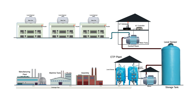
Automated Sewage Water Treatment Plant
Technologies Used